Kia Forte: Blind-Spot Radar / Blind-Spot Radar Unit
Components and components location

1. Blind-Spot Radar Unit (Master)
|
2. Blind-Spot Radar Unit (Slave)
|

1. Blind-Spot Radar Unit (Master)
|
2. Blind-Spot Radar Unit (Slave)
|
Schematic diagrams

Repair procedures
|
lf replacement of the bracket or extension wire of blind-spot radar unit
is required, it is recommended to surely replace the defective part only
with a new one, not the whole blind-spot radar unit.
|
| 1. |
Disconnect the negative (-) battery terminal.
|
| 2. |
Remove the rear bumper assembly.
(Refer to Body - "Rear Bumper Assembly")
|
| 3. |
Disconnect the connector (A) and then remove the blind-spot radar unit
(B) by loosening the nuts.
|
Tightening torque :
8.8 - 10.8 N·m (0.9 - 1.1 kgf·m, 6.5 - 8.0 lb·ft)
|
|
Be careful not to damage the bracket when removing the BCW unit.
|
[4DR]

[5DR]

|
In the following cases, replace the extension wire or bracket.
| 1) |
If the bracket is physically deformed or damaged.
-Remove the bracket (A) from the BCW unit by loosening
the screws.
[4DR]

[5DR]

|
| 2) |
If the connector or wire is damaged.
-Remove the extension wire (A) after separating the mounting
clip.
[4DR]

[5DR]

|
|
|
| 1. |
Install in the reverse order of removal.
| •
|
The shapes of the LH and blind-spot radar units are different.
Therefore, take notice when installing the blind-spot radar
units.
|
| •
|
After the replacement of blind-spot radar unit or bracket
or wire, perform the radar calibration procedures. (If do
not calibrate the sensor angle, it can cause the malfunction
of blind-spot radar system.)
(Refer to Blind-Spot Radar Unit - "Adjustment")
|
|
|
| • |
When a failure code [C2702 (Master)] or [C2703 (Slave)] occurs,
check the following before performing correction.
|
| – |
Check the vehicle condition and whether the radar unit or bracket
is deformed (mounting angle, twisted vehicle body, etc.).
|
| – |
Check the nut tightening. Check if there is any foreign substance.
|
| • |
If you found any problem in the radar unit, bracket, or nut tightening,
correct the problem or replace the component. If there is no problem,
mount the bumper back and perform radar calibration using the KDS.
|
|
Correcting the blind-spot radar angle
| • |
Perform the task on a level place.
|
| • |
Perform the task after checking the tire pressure.
|
|
| 1. |
Remove the rear bumper assembly.
(Refer to Body - "Rear Bumper Assembly")
|
| 2. |
Create the center line of vehicle by using the blind-spot radar unit
correction tool set (09958-3T000 or 09958-3T500).
[9958-3T000]
| (1) |
Attach a vertical plumb (09958-3T010) on the hood, and lower
the plumb (A) to the ground so that it passes through the center
of the emblem.

|
| (2) |
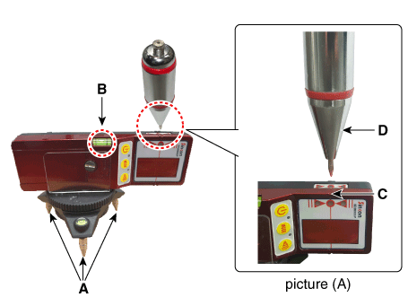
Install an optical receiver (09958-3T020) below the plumb (A).

|
• |
When you install the optical receiver (special
tool : 09958-3T020), adjust the tripod (A) so that
the optical receiver is level with the ground.
|
|
• |
Check the level by looking through the level
checking window (B).
|
|
• |
Make sure that the plumb (D) is positioned above
the hole (C) of the optical receiver as shown in
the picture (A).
|
|
• |
Make sure that the front of the optical receiver
faces the rear of the vehicle.

|
|
|
| (3) |
Attach a vertical plumb (09958-3T010) on the trunk, and lower
the plumb (A) to the ground so that it passes through the center
of the emblem.
[4DR]

[5DR]

|
| (4) |
Install the rear setting jig (09958-3T030) so that its hole is
placed directly under the plumb (A).
[4DR]

[5DR]

|
| (5) |
Place the laser support (09958-3T040) at a location '2m' away
from the rear of the vehicle and install the level laser (09958-3T060)
above the laser support.
[4DR]

[5DR]

|
• |
Move the level laser (09958-3T060) slowly to
left or right to form a center line.
|
|
• |
When the laser beam goes through the hole of
the rear setting jig and the level laser is placed
at the center of the optical receiver, a buzzer
sounds and the center line is formed on.
|
|
|
[9958-3T500]
| (1) |
Attach a vertical plumb (09958-3T010) on the hood, and lower
the plumb (A) to the ground so that it passes through the center
of the emblem.

|
| (2) |
Mark the center point below the plumb (A).

|
| (3) |
Attach a vertical plumb (09958-3T010) on the trunk, and lower
the plumb (A) to the ground so that it passes through the center
of the emblem.
[4DR]

[5DR]

|
| (4) |
Mark the center point below the plumb (A).
[4DR]

[5DR]

|
| (5) |
Pass the string through the bottom of the vehicle from the rear
of the vehicle to the front and fix the string to the center point
(A) of the front of the vehicle.
|
| (6) |
Fix the string to the point (C) about 1.5 - 2m from the back
of the vehicle so that it passes the rear center point (B).

|
|
| 3. |
Tighten the nuts after removing the BCW radar absorber (A) by loosening
the mounting nuts. (Only 5DR)

|
| 4. |
Mount the fixing adaptor (09958-3T080) on the radar unit and fix the
level laser (09958-3T070).
[4DR]

[5DR]

|
| 5. |
Measure the horizontal angle.
|
Specified angle : 4DR : 54° / 5DR : 52°
|
[9958-3T000]
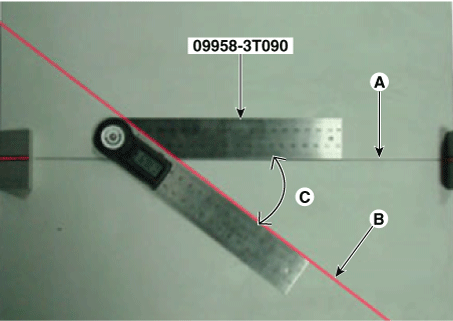
| (1) |
Install an angle measuring plate (09958-3T050) at a location
where the center line laser beam (A) and the horizontal laser beam
(B) cross each other.

|
| (2) |
Measure the angle (C) between the center line (A) of the angle
measuring plate and the horizontal laser beam (B) using a digital
protractor (09958-3T090).

|
[9958-3T500]
| (1) |
Measure the angle (C) between the center line (A) of the angle
measuring plate and the horizontal laser beam (B) using a digital
protractor (09958-3T090).

|
|
| 6. |
Measure the vertical angle of the blind-spot radar unit by using the
digital inclinometer (09958-3T100).

|
| 7. |
Install the BCW radar absorber from the BCW unit. (Only 5DR)
|
| 8. |
After checking and correcting the blind-spot radar unit angle, perform
the BCW radar calibration procedure using the KDS.


|
Specifications
Specifications
Items
Specification
Rated voltage
DC 12 V
Operating voltage
9 - 16 V
...
Schematic diagrams
Circuit Diagram
Repair procedures
Inspection
1.
Disconnect the BCW switch connector from the side crash pad switch.
...
Other information:
First secure the child restraint with
the LATCH lower anchors or the seat
belt. If the child restraint manufacturer
recommends that the top tether
strap be attached, attach and tighten
the top tether strap to the top tether
strap anchor.
Child restraint hook holders are
located on t ...
Repair procedures
Removal
1.
Disconnect the negative (-) battery terminal.
2.
Remove the front bumper assembly.
(Refer to Body - "Front Bumper assembly")
3.
Remove the front fog lamp (A) by loosening the screws ...


 Blind-Spot Radar
 Blind-Spot Radar Switch


